The hidden cost of hand-typed coordinates
Hunting dimensions, recalculating from your zero, bolt circles, typing the same points three times: where transfer errors come from, and a checklist that works without software.
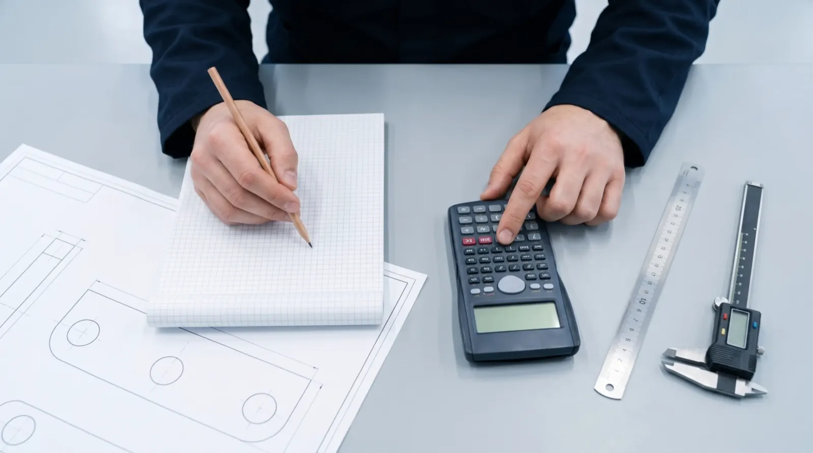
In a lot of shops with a big horizontal boring mill, the program is written at the control, by the machinist, from the drawing. The machining strategy is usually the easy part: they know the machine and the tools. The slow part is the numbers. Every hole position has to be found on the drawing, converted to the machine’s zero and typed in, often more than once.
Nobody puts this on a quote, because it is “just reading the drawing”. It is worth looking at what that really involves.
Where the time goes
Finding the dimension
A base plate or a welded frame can carry dozens of holes on one view: several thread sizes, dowel holes, clearance holes, each group defined by a letter in a hole table and a chain of dimensions. On a crowded view the groups mix. You read a dimension, follow it to the wrong extension line, and the mistake looks perfectly reasonable on paper.
Recalculating from your zero
The designer dimensions from their datum. The machinist works from the zero they probe: a corner, an edge, the centre of a bore. Every coordinate becomes “drawing dimension plus or minus an offset”, and chained dimensions add up their own errors. Turn the part over for the second setup and the signs change.
Bolt circles
Take our demo plate DM-2041 (invented, like every example here): four M16 holes on a Ø125 circle, at 45°, with the centre at X 320, Y 400. Each hole is the centre plus or minus 62.5 × sin 45° = 44.194, in both X and Y:
| Hole | X | Y |
|---|---|---|
| 1 | 320 − 44.194 = 275.806 | 400 − 44.194 = 355.806 |
| 2 | 275.806 | 444.194 |
| 3 | 364.194 | 444.194 |
| 4 | 364.194 | 355.806 |
Every point is a calculation. A wrong sign puts a hole 88.388 mm from where it should be. A calculator left in radians gives 53.181 instead of 44.194, and the resulting position still looks plausible enough to drill.
Dimensions that are not there
Some holes have no dimension on the paper at all. The programmer looks in the DXF, or asks the colleague who has the CAD model to measure the position and send it over. Then waits.
The same list, three times
A threaded hole is drilled, chamfered and tapped. If the program repeats the point list for every tool, the same coordinates are typed three times. DM-2041 has 38 holes: 28 threaded holes that need three tools each, and 10 plain holes. That is 94 positions typed by hand. With one subprogram per group, it would be 38.
Each retyped position is a fresh chance for a typo, and a typo in the tapping list after a correct drilling list is the worst kind: the tap meets solid metal.
What one wrong digit costs
A typical part in our pilot shop is a welded part of over two tonnes, machined for about 24 hours. The cost of a transfer error is not the minutes spent typing. It is a wrong hole in a part that already has a day of machine time in it: a weld repair, a scrapped part, a new setup by crane, or a crash in the worst case.
We haven’t yet measured how many hours coordinate transfer takes in a typical shop. That is one of the things the pilot is for. But anyone who has checked a list of coordinates for the third time knows where the hours go.
A checklist for fewer transfer errors
None of this needs software.
- Write the zero on the drawing first. Which corner or edge is X0 Y0, which face is Z0. Put the same on the setup sheet.
- Convert everything in one table before you touch the control. Columns: drawing value, offset, result. Don’t convert in your head at the keyboard.
- Calculate bolt circles in a spreadsheet, from the centre, radius and angle. If you use a calculator, check that it is in degrees.
- Check radius and symmetry. Each hole on the circle should be 62.5 from the centre: √(44.194² + 44.194²) ≈ 62.5. Opposite holes should add up to twice the centre: 275.806 + 364.194 = 640 = 2 × 320.
- Type each point list once. Put it in a subprogram (
LBL "D14"…LBL 0) and call it for drilling, chamfering and tapping withCALL LBL "D14". - Count. The hole table says 4x: there should be four positions in the program.
- Don’t drill from a scaled measurement. If a dimension is missing, ask the customer for it, or for the model. Mark anything you measured off a print as approximate.
- Run the program in Test Run on the control, with
BLK FORMset to the real blank, and compare the picture with the drawing. - Read the coordinates back to a second person who has the drawing in front of them.
- Keep the calculation sheet with the program. The next revision starts from it.
Where Metallovy fits
Metallovy does steps 2 to 6 from the DXF and STEP. It finds the holes, groups them by the drawing’s hole table with thread, depth and side, recalculates everything from the zero you choose, writes one LBL per group in your shop’s style, and checks the program against the part. Every number carries its source, so step 9 becomes “show me where this came from” rather than “let me calculate it again”.
On a real order, it found 68 of 68 points of the shop’s own hand-written program, within 0.01 mm. The machinist still checks the program, and still takes it to the machine on a USB stick.
Try it on one of your own drawings, ideally the one with the most holes on a single view.